|
|
|
Kto jest w sklepie?
Sklep przegląda 6043 gości |
|
Kategorie
|
|
Informacje
|
|
Polecamy
|
|
|
 |
|
|
Dla tego produktu nie napisano jeszcze recenzji!
 ;
...instruction is ok.
...instrukcja jest ok.
Thanks/Dzięki
;
Documentation made available quickly and It is good quality. Thanks.
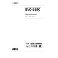
ADJUSTMENT <TUNER / DECK / FRONT>
< TUNER SECTION >
1. Clock frequency Check Settings : � Test point : TP2 (CLK) Method : Set to MW 1602kHz and check that the test point is 2052kHz ± 45Hz. 2. MW VT Adjustment Settings : � Test point : TP1 (VT) � Adjustment location : L953 Method : Set to MW 1602kHz and adjust L953 so that the test point becomes 8.0V ± 0.05V. Then set to MW 531kHz and check that the test point is more than 0.3V. 3. MW Tracking Adjustment Settings : � Test point : TP8 (Lch), TP9 (Rch) � Adjustment location : L952 .................................................... 603kHz TC941 ................................................ 1404kHz Method : Set up TC941 to center before adjustment. The level at 603kHz is adjusted to MAX. by L952. Then the level at 1404kHz is adjusted to MAX. by TC941. 4. SW VT Adjustment Settings : � Test point : TP1 (VT) � Adjustment location : L942 Method : Set to SW 17.9MHz and adjust L942 so that the test point becomes 8.0V ± 0.05V. Then set to SW 5.9MHz and check that the test point is more than 0.3V. 5. SW Tracking Adjustment Settings : � Test point : TP8 (Lch), TP9 (Rch) � Adjustment location : L941 .................................................... 5.9MHz TC943 ................................................ 17.9MHz Method : Set up TC943 to center before adjustment. The level at 5.9MHz is adjusted to MAX. by L941. Then the level at 17.9MHz is adjusted to MAX. by TC941. 6. AM IF Adjustment Settings : � Test point : TP8 (Lch), TP9 (Rch) � Adjustment location : L802 .................................................... 450kHz 7. FM VT Check Settings : � Test point : TP1 (VT) Method : Set to FM 87.5MHz and check that the test point is more than 0.5V. Then set to FM 108.0MHz and check that the test point is less than 8.0V. 8. FM Tracking Check Settings : � Test point : TP8 (Lch), TP9 (Rch) Method : Set to FM 98.0MHz and check that the test point is less than 9dBµV. 9. DC Balance / Mono Distortion Adjustment Settings : � Test point : TP3, TP4 (DC) � Adjustment location : L801 � Input level : 60dBµV Method : Set to FM 98.0MHz and adjust L801 so that the voltage between TP3 and TP4 becomes 0V ± 0.3V. Then check that the distortion is less than 1.3%. 10. Output Level Check <MW> Settings : � Test point : TP8 (Lch), TP9 (Rch) � Input level : 74dBµV Method : Set to AM(MW) 999kHz and check that the test point is 74mV ± 3dB. <FM> Settings : � Test point : TP8 (Lch), TP9 (Rch) � Input level : 60dBµV Method : Set to FM 98.0MHz and check that the test point is 320mV ± 3dB. 11. FM Separation Check Settings : � Test point : TP8 (Lch), TP9 (Rch) � Input level : 60dBµV Method : Set to FM 98.0MHz and check that the test point is more than 25dB.
< DECK SECTION >
12. Tape Speed Adjustment (DECK 2) Settings : � Test tape : TTA�100 � Test point : Method : TP8 (Lch), TP9 (Rch) � Adjustment location : SFR1 Play back the 3kHz signal of the test tape and adjust SFR1 so that the test point becomes 3000Hz ± 5Hz (FWD) and FWD SPEED ± 45Hz (REV).
13. Head Azimuth Adjustment (DECK 1, DECK 2) Settings : � Test tape : TTA�330 � Test point : TP8 (Lch), TP9 (Rch) � Adjustment location : Head azimuth Method : adjustment screw Play back (FWD) the 8kHz signal of the test tape and adjust screw so that the output becomes maximum. Next, perform on REV PLAY mode.
14. PB Frequency Response Check (DECK 1, DECK 2) Settings : � Test tape : TTA�330 � Test point : TP8 (Lch), TP9 (Rch) Method : Play back the 315Hz and 8kHz signals of the test tape and check that the output ratio of the 8kHz signal with respect to that of the 315Hz signal is 0dB ± 5.0dB. 15. PB Sensitivity Check (DECK 1, DECK 2) Settings : � Test tape : � Test point : Method : TTA�200 TP8 (Lch), TP9 (Rch)
Play back the test tape and check that the output level of the test point is 110mV ± 3.0dB.
16. REC/PB Frequency Response Adjustment (DECK 2) Settings : � Test tape : TTA�602 � Test point : � Input signal : TP8 (Lch), TP9 (Rch) 1kHz / 8kHz (�20VU / �26dBV) � Adjustment location : SFR451 (Lch) SFR452 (Rch) Method : Apply a 1kHz signal and REC mode. Then adjust OSC attenuator so that the output level at the TP8, TP9 becomes 5.5mV ~ 9.5mV. Record and play back the 1kHz and 8kHz signals and adjust SFRs so that the output of the 8kHz signals becomes 0dB ± 0.5dB with respect to that of the 1kHz signal.
� 28 �
|
|
|
> |
|